As winner of numerous international awards, Bruschi Spa is known for its innovative approach in design and technology. We are glad to share our insights and experiences with the industry members.
Optimizing die casting engineering for cost reduction
Industry 4.0 tries to gather every phase of production process into simulation. In particular in die casting engineering, simulation has to consider several points: productive plant, die casting tools, automation tools, cooling tools, secondary operation tools.
Optimizing die casting engineering
Die casting engineering optimization is not only related to simplify the process and cost reduction during different phases of die casting process, but also their integration with it.
For this reason integrated analysis models have a fundamental role during die casting engineering.
Technology, during the past few years, allowed to reach an important level in developing tools for design, production and control of the process: the aim was to made a complex structure where tools were in constant collaboration among them.
Productive plant, die casting tools, automation tools, cooling tools, and secondary operation tools are necessary to design a process that is similar to reality.
However often designers are tempted to obtain the optimal process for a particular product. In this way zinc die casting manufacturers do not consider physical limits imposed by usual die casting process and its tools.
The importance of simulation in cost reduction
Cost reduction in die casting engineering can be achieved widening simulation phase. In fact simulation is a key point of the process that is developed only at the beginning of industrialization of the product or component.
Every improvement adopted in this phase allows to reach an important saving during productive life of a component or product thanks to a small investment.
Integrated model in process simulation
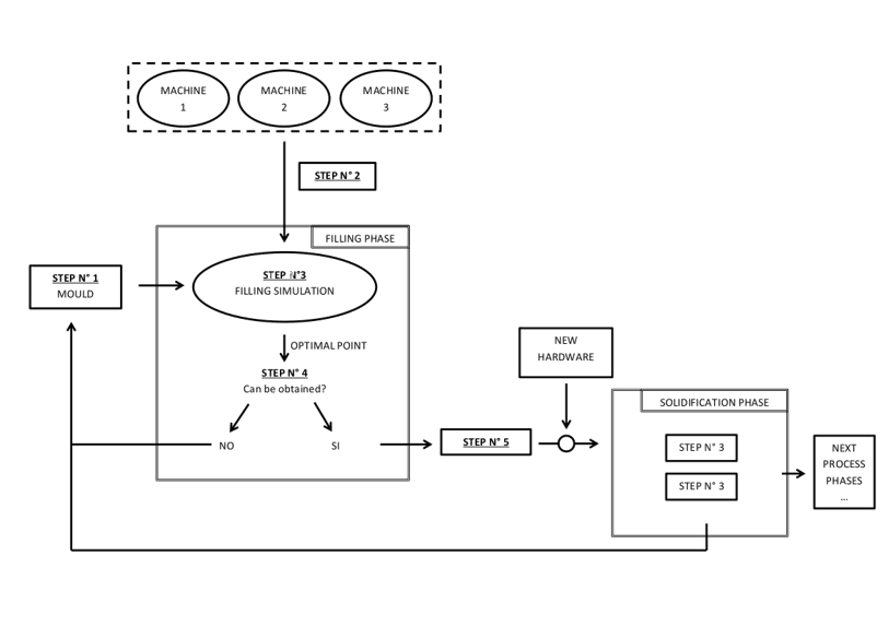
Hereunder is explained an approach to integrate every phase of die casting process in simulation analysis.
Once the designer has decided phases that are going to be part of the productive process uses simulation tools to optimize them and reduce costs and time.
First of all is important to consider different systems: the one that regards machine and the one that concerns die casting: at the beginning they compose the system hardware and they can be used for an iterative simulation of every phase of die casting process.

Step 1: A first design approach to moulds
In this step is important to define the mould from a mechanical and thermo-fluid dynamic viewpoint. Taking into consideration clients’ requests, component characteristics and critical points, the designer has to point out some rules to be followed in order to produce a correct and functional mould. First of all the designer has to reduce complexity of the mould, increase ratio between casting weight and waste materials and positioning gates near important areas for aesthetic or structural requirements.
Step 2: Define die casting machineConsidering mould dimensions and liquid metal thrust, the designer has to choose the type of machine that suits better the process.
At the same time when the designer chooses the type of machine, need also to consider the stroke diameters and working pressure.
Step 3: Simulation of this stepThere are different kind of simulation that change related to different process phase analyzed. For example the first step that has to be studied with CFD method is filling the cavity. During next step other methods can be used such as CFD method for solidification of the metal, FEM analysis for casting ejection, automation software to handle components or casting, thermal analysis one or multi dimensional for quenching. In every approach that the designer will choose, feasible boundary conditions must be identified with the aim of reaching an optimal state.
Step 4: Run the iteration or go back to the beginningIf the process simulated in this step is obtainable from the defined system hardware, the designer can move to next phase; if not the designer needs to go back to phase 1 and modify the mould or the machine choice.
Step 5: Entering the next phaseIn this step new hardware such as cutting machine or cooling system can be added to the algorithm.
Step 6: Return to previous stepThe iteration cycle restarts from step 3 and 4 and proceed to next process phases. After simulation, if the optimal condition is not reachable with hardware defined before, is necessary to intervene and go back to step 1.
Thanks to this integrated system, the process is optimized for every single step because at every iteration cycle the algorithm can change the hardware defined at the very beginning of the process.
Process stability
The aim of the previous algorithm is to identify an optimal cycle time that can be supported by the hardware system.
However to make the process stable, this is not enough. Variables of the system have physical limits that cannot be overtaken and that can be represented with a Cartesian coordinate system edges of a multidimensional solid. As long as the point that represents the productive process is inside the solid and distant from the edges the process is stable.
This process can be defined unstable if some part of the inside system such as thermos regulation machine do not reach the correct temperature indicated in its technical sheet.
If you are using simulation to design or improve your die casting moulds and processes, please share your experience with us writing a comment here below.
To get updates on trends and innovations in the Zinc Die Casting industry, you are welcome to subscribe to our blog.


